How to Control Asphalt Milling Depth to the Millimeter
Similar to systems for earthmoving equipment, these GPS- and software-driven systems have become plug-and-play staples for savvy managers on milling (and subsequent paving) jobs.
As in performing earthwork to grade, accuracy is the goal. Efficiencies, speed, and cost savings follow. Traditional milling, using stringlines and markings, has its limitations.
“The operator needs to work to the design for the new surface, removing the right depths in the right places,” says Matthias Schmidt, senior product portfolio manager, machine control division, Leica Geostystems. “Traditionally, this is done by following sprayed marks manually laid out by a surveyor. This prework is time-consuming and subject to error. To be carried out safely, the road needs to be closed and often the surveyor needs to work at night to minimize disruption.
“This makes the job difficult, as do weather conditions; spraymarks can get washed away by rain, and wind can make marking inaccurate,” Schmidt says. “Once the design has been marked, it can be difficult for operators to see—it gets hidden by other machinery onsite or might be difficult to read from their machine. Any inaccuracies lead to the machine operator either taking too much asphalt away, which subsequently means the area will need to be overfilled and the project will be more expensive than it should be, or not taking enough asphalt and the new surface layers being of poorer quality. Another risk, when milling deeper than required, is damaging the structural subbase layers.”
Leica is one of three major companies providing 3D machine control systems for milling machines. It has a system, Leica iCon site milling pilot application, specifically designed as a first step toward digitally controlled milling.
“Using positioning data from a GNSS receiver such as the iCon gps 60 and iCON gps 70 on the machine, the milling pilot calculates the difference between the existing and the design surface as the cold planer moves over the area that is being milled,” Schmidt says. “On the iCon CC80 field controller in the cabin, the iCon site software indicates a two-step preview of set and cross slope values at predicted points, ahead of the current position. As this process is manual, the indicated values must be entered into the machine’s leveling controller by the operator.”
Managers can then progress to the more accurate and faster 3D machine control solution. “This is where the cold planer is equipped with machine control technology that controls how much to mill,” Schmidt says. “3D systems can reproduce road grades and slopes far more accurately, making it easier to achieve complex designs, ultimately improving the smoothness of the final pavement. Leica Geosystems offers two different methods of 3D stringless milling solutions: profile milling and differential milling.”
Schmidt says that in profile milling, the 3D solution adjusts milling depth and slope based on data sent from a total station.
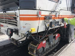
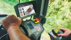
Above: Milling machine manufacturers have made it easy to bolt on the sensors and monitors necessary to carry grade. Most are at a worker’s level.
“The surveyor or the machine operator uploads the digital design file for the road into Leica MC1 machine control software,” he says. “The software compares the design model to the actual position of the machine’s cutting edge and assists the operator to position the machine to achieve the planned design. An active total station tracks the position of the cold planer in 3D, and MC1 on the machine verifies the elevation and slope against the design. The depth of asphalt to cut is sent to the machine controller. It is shown on the operator’s tablet interface that they have in the cab and controls the hydraulic response on the machine. This eliminates the need for a surveyor to make any marks or stringlines on site, or for the operator to follow man-made markers and control the adjustments.”
Automatic differential milling can be done using the iCon site milling pilot, and it uses two data sources to automate the differential process: the design for the road and the as-built model of the road that describes the current surface.
“The source of the as-built model could be from measurements taken using a total station, a 3D laser scanner, or a mobile mapping solution,” Schmidt says. “A quick way to create the as-built model is to fit a mobile mapping solution to a vehicle and drive it along the road that needs to be resurfaced. Alternatively, a ground penetrating radar solution can be used, which provides data about the different layers with the most important information for the proper execution of the project, such as depth and thickness of reinforcement cover, concrete slab, and asphalt, detection of areas affected by corrosion, and detection of rebars.”
The iCon software takes the design and the as-built model and looks at the differential between them, calculating what needs to be removed to create the desired surface. “The Leica iCon GPS 60 or GPS 70 smart antenna is used to work out the location of the milling machine and where it is in relation to the design,” Schmidt says. “The iCon site milling pilot app calculates the milling depth values and the cross slope at the position of the machine from the design differences. The app sends this information via the Leica iCon CC80 tablet to the [milling] machine controller, which controls the hydraulic response on the machine.”
Topcon’s 3D-MC Milling allows a 3D design model to dictate and control milling depth. It allows millimeter-level accuracy thanks to GPS, has a 2,400-meter horizontal working range, and a 40-meter vertical working range. Multiple users in the same zone can mill horizontally, vertically, or with combined transitions.
How does machine control work on asphalt milling machines?
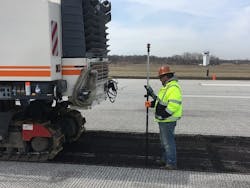
A runway rehabilitation project at Toledo, Ohio, Express Airport is an example of how the system works.
“The project entails mostly a mill/fill to design grade,” says Mike Kreig, project manager for Gerken Paving in Toledo. “The engineer requires us to hit a design grade on the final surface. It also has a design grade to mill to, so it’s an approximately three-inch milling project with two courses, a leveling course and then a surface course.”
Tim Winch, Gerken’s grading foreman, is the man on the ground using the system. He often walks with the milling machine, checking progress and accuracy with just a glance at a monitor. “They expect a really smooth surface when it’s all said and done—that’s why we’re doing it with a 3D millimeter system. It’s a lot more accurate than what we can get with our normal system,” he says.
“The advantage that we noticed right off the bat was that you can just let the machines do the work,” Kreig says. “You can literally go anywhere out on the project and find your grade, whether that’s a surface grade for your pavement, or a cut grade for the mill. You can catch grade wherever you’re at, you don’t have to have a parallel line to catch grade as you would with stringline.”
Managers will find cost savings and other efficiencies at ground level.
“Some of those stringlines, they can sag and you’ve got to recheck,” Winch says. “Where at least with this—those satellites—they don’t lie. I don’t know how it works, but it does and it’s very efficient.”
“Another advantage to using the millimeter GPS is being able to eliminate the cost of the stringline, which is a huge advantage and time consideration here on the project,” Kreig says. “We can get out and set things up in the morning and work throughout the day with really just a few battery changes on some of the transmitters. We’re able to work throughout the day without any interruption versus moving stringline, resetting grading, and having to stop our operation. So, our production really increased just being able to utilize the millimeter technology.”
Winch cited peace of mind as another advantage. “It was just so nice to be able to walk along and not have to worry about a bump. If it all didn’t get swept off, if my ski went over it, still, there are no bumps in [the end result]. It made life a little nicer for us on the ground,” he says.
Gerken was able to remove the machine control equipment from the milling machine and use it for the paving portion of the job.
“The advantages that we’ve experienced through paving have been very similar to the milling advantages, where there’s not an interruption, we constantly carry grade, and we’re able to continue at the same speeds and even higher production rates with the process of paving,” Kreig says.
“[The system is] telling that machine what to do, where to do it, and it’s real accurate,” Winch says. “You’ve got down to the final course and all they had to do was come in and lay an inch and a half and it makes it real nice when you don’t have to worry about a bump in the road. It was already perfect for them on their final [laydown].”
Trimble PCS 900 for milling machines uses a 3D design model, the company’s SPS930 Universal Total Station, and add-on machine sensors to mill at a fixed or variable depth, depending on job specifications.
The 3D design is displayed to the milling machine operator showing areas that are on, above, or below ideal grade. The system compares the actual drum position and slope with the digital design and automatically guides the milling drum to cut the ideal depth and slope without manual adjustments or stringlines.
The company says its system will help milling machine performance and truck logistics; by only milling to the the depth required, the machine will burn less fuel and experience less tooth wear. Also, without stringlines and stakes hindering trucks, shorter lane shutdowns are possible. Fewer trucks may be required to remove waste material, which is another potential cost savings.
