How to crown a road with a grader
"One of the biggest problems we find in the field is that many motor grader operators don't have the experience in construction to know how to approach the job correctly," says Henry Pietens, training and marketing support manager for motor graders at Volvo. "If you drive gravel roads much, it's apparent that there are a lot of intermediate-level operators [working road maintenance] who don't understand the importance of proper crown and slope. We end up with flat roads with potholes and washboard."
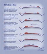
The most important aspect of road maintenance is providing good drainage. It starts with the road crown in straight sections and super elevation in curves. A straight road's wear surface should rise toward the centerline ¼- to ½-inch per horizontal foot, or about a 3 percent slope from the shoulder to the center of the road. This will vary with the type of gravel used in the surface and expected annual rainfall. Curved road surfaces should be flat, but inclined on a 6 percent slope down to the inside of the corner.
Ditch slopes should vary depending on the type of road being constructed, the soil type, ditch depth, and width of available right of way. Whenever possible, though, ditch slopes should be flatter than 2:1, or 50 percent.
Vee-ditches should be at least 2 feet lower than the road wear surface, but depth will vary depending on road and soil type and available right of way. A flat-bottom ditch can handle large amounts of rain or snowfall, and cutting flat-bottomed ditches can supply extra material if it is needed to elevate the road. In regions subject to extreme precipitation, raise the travel surface high enough to prevent water from seeping under the road. A raised surface also allows snow to blow off the road, reducing drifting.
"We also find that a lot of operators are not familiar with all the features on the machine," says Pietens, "and they can't begin to maximize the machine's potential if they don't use all of the features that contribute to efficiency."
How to select grader speed and moldboard angle
"Motor graders can be used to do a number of different tasks, some of which are better suited to high speeds than others," says Matt Turner, manager of Caterpillar's demonstration and learning center. "When you're doing delicate work or pioneering work, you have to go slow — use the first two or three gears. Sweeping snow or knocking the rocks and washboard off a gravel road you can do fast."
Most grading is done at moldboard angles from 10 to 45 degrees.
"Too many grader operators will work without enough angle on the blade. They end up pushing material like a dozer," says Scott Mennenga, motor grader instructor with Local 150 of the International Union of Operating Engineers in northern Illinois. "You want a nice smooth motion to get a windrow rolling off the end of the blade."
Grading is most efficient when material is rolling across the blade from its leading edge (the toe) to its trailing edge (heel). If the rolling action dies or material stops flowing, increase the blade angle.
"You can tell right away how experienced an operator is by how he sets up the blade — is he putting it down in the dirt and getting the work done, or is he pussy-footing around?" Mennenga says. "When you're making the first passes, you want to get that blade down on the ground, get a nice medium windrow going and get everything knocked down flat. You might have to make several passes on a road before you start to fine tune."
Moldboard tip has something to do with depth of cut. Most grading passes should start with the moldboard top positioned about 2 inches ahead of the cutting edge. For better penetration, start with the top of the moldboard more forward, the cutting edge more perpendicular with the grade.
Tip the moldboard forward or back slightly to start and maintain the desired cutting action and to roll material smoothly across the blade.
Tipping the moldboard forward or back also changes depth of cut across the entire moldboard.
Leaning the front wheels can also vary the cutting depth, but this feature is much more important to keeping the grader pulling in a straight line. The top of the front wheels are normally leaned in the direction that material comes off the moldboard.
Motor grader wheel positioning
"You can fine grade with the wheels straight up and down," says Mennenga, "but you want to get those front wheels leaning in the direction of the windrow, working with you, when the windrow gets heavy."
Set the front wheels in a vertical position when working side slopes or ditches or lean them up the hill for better steering control. Or when working across a slope using articulation, you can lean the wheels down the slope to prevent the front-axle from reaching its oscillating limit. An operator can also use wheel lean to make slight steering corrections without taking his hands off the hydraulic controls.
Many grading jobs can be done with the motor-grader frame locked straight — most finishing work, light to medium windrows, some ditch cutting, ripping and scarifier work, for example. But manufacturers designed frame articulation to add flexibility that makes today's graders capable of much more than rigid machines.
"When you're carrying a nice heavy windrow, you'll want to use articulation to put more power behind the blade," says Mennenga. "If you keep a straight machine, it might struggle a little. Operators will notice if they articulate the wrong way, the machine will slide away from windrow."
As the front of the machine starts to slide away from the moldboard heel, articulate the back frame toward the toe to counteract the side load.
Flexing the frame also improves the grader's maneuverability. Articulating into turns gives the shortest turn radius for close-quarter work, cul-de-sacs or corners. Articulating also allows steering the leading end when backing the machine.
Crab steering — articulating the frame and steering the front wheels in the same direction — improves the grader's side-slope capability, and allows the tandems to be offset away from edge fill to prevent rutting, or keeps them on a smooth surface for faster finishing.
Articulating the rear frame toward the toe of the moldboard approximately 2 to 5 degrees (1 to 1½ times the width of the tire) will often reduce the machine's tendency to bounce. This crab mode is extremely effective when cutting washboard from a road's wear surface. In the crab mode, the grader's front axle is no longer perpendicular to the direction of travel. This puts one front tire slightly ahead of the other. One tire rides up on top of a corrugation in the road while the other is still in the bottom. As the tires roll up and down through the washboard, the front axle will pivot, keeping the front frame stable. The degree of articulation required to make this technique work will vary with the space between corrugations.
Be careful: Caterpillar warns against using crab mode when scarifying washboard roads. Because the frame is not traveling parallel to the direction of travel in crab mode, it could bend the scarifier shanks or linkage.
Another caution for operators who have little experience with articulated graders is to watch both ends of the blade when articulating.
"If you're delivering a nice windrow right outside the rear tires, the blade's heel is going to be near that front tandem," says Mennenga. "You have to make sure the blade is far enough away that when you do articulate you don't slash the tire with the blade."
How to use a motor grader on stone
For best results with stone surfaces, dress the road when moisture is present: after a rain or after the road has been sprayed by a water wagon. Drag the surface when hard and dry, with the cutting edge near 90 degrees to the surface.
Cut to the depth of major potholes. Don't fill them with loose material because traffic will quickly displace the loose material and the holes will reform.
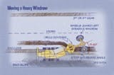
A grader's center-shift link bar is designed to increase the moldboard's reach from the centerline of the machine. Maintenance work is normally done with the center-shift lock pin in the center position, and the drawbar and circle centered under the main frame. But repositioning the link bar will increase the motor grader's productivity when ditching, backsloping and moving large windrows.
Offsetting the circle allows you to keep the mainframe running on a level surface at the top of the ditch or base of a slope while the moldboard cuts beside the machine. When moving large windrows with the link bar repositioned either side of center, the moldboard can be adjusted to a steep angle and it will still leave the windrow outside the tandems.
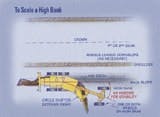
There are several holes or positions in the link bar allowing the operator to choose how far to offset the circle from the frame's center line. It is recommended to use the first and second holes for cleaning shallow ditches, processing and moving large windrows, and combined with articulation to build narrow, flat-bottom ditches and backfill curb radii.
Begin to reposition the circle in these first offset positions by shifting the drawbar as far as possible towards the ditch or slope to be graded. Ground the moldboard by placing both lift levers in the float position. Release the center-shift lock pin (on most machines a light on the control panel will illuminate when the pin is retracted). With the levers still in the float position, move the center-shift lever in the direction opposite that used before retracting the pin. For example, if the lever was pulled back to shift the drawbar right, now push the lever forward.
The center-shift cylinder will roll the linkage around freely, moving the link bar sideways. Line up the link-bar hole with the hole in the carriage and re-insert the pin. When the light on the console goes off, the pin is in. Now you can sideshift the drawbar towards the slope to be cut and use the lift cylinders to adjust the slope angle.
The hole in the link bar farthest from center is recommended for use when cutting ditch back slopes and high banks, cleaning deep ditches, grading and dressing fill slopes, disposing of sod/oversize rock on back slopes, and for use with articulation to grade steep slopes.
To offset the circle extreme right, ground the moldboard on the right side and use the same process as before to release the pin. Once the pin is released, simultaneously push forward on both the right lift and the center-shift levers and pull back on the left lift lever. Line up the holes and insert the pin.
When grading, use only enough down pressure to accomplish the task. Excessive down pressure on a hard, dry surface eats up cutting edges, demands more horsepower and fuel, and cuts productivity. Sliding and tire spinning increases tire wear. Extreme down pressure may even splinter the cutting edges, which could cause tire damage.
Mennenga recommends operators who are maintaining roads practice feeling for variations in grade.
"As the front tires run over rough terrain, they will go up and down," he says. "You want the blade down on the ground carrying material, but as the front end goes down, you're going to need to fill that area. You have to raise that blade just a little bit when the wheels drop. Then bring the blade back down when the wheels come up.
"But you don't want to overfill either," Mennenga adds. "You have to be able to feel it.
"The motor grader is a nice long machine, and when the blade is full, it does carry material over small dips and make them smoother," says Mennenga. "But it won't correct for 3/10ths to 4/10ths variations without adjusting the blade.
"Any time you're applying a finished grade, you should build it about a 10th or so high, so that when you make your final pass you have some material on the blade," Mennenga concludes. "If not, on the final passes, you will be short on material."


